HOW REPUBLIC’S EXPERIMENTAL TURBOPROP FIGHTER BECAME THE LOUDEST AIRCRAFT EVER BUILT
When the renowned designer Alexander Kartveli began work on the future P-84 based on a General Operational Requirement issued by the US Army Air Force on September 11, 1944, he could scarcely have imagined that between 1945 and 1958, Republic Aviation Corporation, with assistance from General Motors, would construct nearly 8,000 F-84s across all variants. This remarkable production figure was achieved thanks to manufacturing capabilities reaching 200 aircraft per month—a rate that would make today’s aerospace manufacturers envious. Of course, substantial evolution occurred between versions, with virtually nothing from the earliest models appearing on the later variants. The fuselage, cockpit, tail assemblies, wing configuration and powerplants were all extensively modified, with only the basic F-84 designation remaining unchanged—primarily for obscure budgetary presentation purposes.
Unlike its contemporary, the North American F-86 Sabre, which never served as a platform for experimental programs venturing beyond conventional fighter design, the F-84 became associated with several extraordinarily innovative projects that triggered further transformations. These included wing-tip mounted parasite fighters (Operation Tom-Tom) and reconnaissance aircraft carried within a B-36 bomber’s weapons bay (Operation Ficon). However, none proved as radical as the modifications applied to the XF-84H, which became the last “Thunder” variant to employ a propeller.
A SUPERSONIC PROPELLER
By the conclusion of World War II, turbojet development had enabled cutting-edge aircraft to achieve performance levels previously unattainable with piston-engine powerplants.
Since propeller efficiency during this era declined substantially at high Mach numbers, the technology appeared to have reached its practical limits, at least for combat aircraft. Naturally, aircraft manufacturers worldwide redirected their research toward pure jet designs, despite the significant challenges posed by unreliable and extremely fuel-hungry engines that forced designers to dramatically increase internal fuel capacity while simultaneously accepting greatly reduced operational range. In the United States, however, certain researchers—recognizing the inherent advantages of propellers—began investigating the feasibility of propeller systems capable of operating efficiently at speeds far exceeding those attainable with piston engines. Three principal concepts guided their research: first, designing blades with nearly perfect aerodynamic geometry; second, utilizing airfoil profiles as thin as physically possible; and third, operating the propeller at extremely high RPM so that the outboard sections of the blades would travel at supersonic speeds. This advanced propeller concept would necessarily be paired with a turboprop engine—a powerplant type that would prove exceptionally challenging to develop, particularly in the United States.
After the supersonic propeller’s potential had been demonstrated in National Advisory Committee for Aeronautics (NACA) wind tunnels, the next phase required testing under actual flight conditions using a high-performance aircraft. In July 1949, the US Air Force decided to modify the first McDonnell XF-88 Voodoo prototype by installing an Allison XT38-A-5 turboprop in its nose section. The approach involved utilizing an otherwise obsolete prototype as a flying test bed, which—thanks to its twin turbojet engines—could safely perform the experimental mission. In this modified configuration, it completed its maiden flight on April 14, 1953, and by April 24, the turboprop was successfully operated in flight for the first time. Parallel to this cautious and prudent approach—the XF-88B would ultimately serve NACA for more than four years—the Air Force issued a request for proposals in January 1950 seeking manufacturers to convert an existing jet aircraft to rely exclusively on turboprop power with a supersonic propeller. Following thorough evaluation of several proposals meeting Air Command technical requirements, the Air Research and Development Command awarded Contract No. AF 33(038)-20501 to Republic Aviation for converting two RF-84F-26-RE aircraft into XF-84H testbeds.
This selection was justified by the RF-84F’s solid nose section, which appeared ideally suited for turboprop installation with air intakes that could be readily adapted from those already positioned in the wings of the Thunderflash. However, Republic’s engineers quickly encountered formidable challenges because the airframe they had selected was never designed to withstand the tremendous torque generated by a high-speed propeller. Stability and flight control issues appeared insurmountable with the initial design parameters, and wind tunnel testing with powered models proved disastrous—the XF-84H demonstrated complete instability and uncontrollability. To address these critical deficiencies, extensive modifications were developed with Air Research and Development Command approval. Ultimately, the redesigned aircraft diverged so dramatically from the original concept that it warranted an entirely new designation: XF-106.
Only the canopy and wing section from the RF-84F remained in the final design. Why, then, maintain the XF-84H designation? During budget discussions, the Air Force strategically presented spending programs by aircraft type. It proved far simpler to secure funding for what appeared to be a straightforward F-84 modification—buried within the substantial Thunderstreak and Thunderflash procurement—than to attract scrutiny from vigilant lawmakers who might question an entirely new XF-106 fighter concept featuring what would have seemed like an anachronistic propeller system in 1951-1952. This administrative sleight-of-hand had precedent with the F-84F, whose prototype initially carried the YF-96 designation. However, virtually no components were shared between the straight-wing Thunderjet and swept-wing Thunderstreak.
NOTHING SIMPLE: THE SUPERSONIC PROPELLER OF THE XF-84H
The XT54-A-I was selected as the powerplant, and on June 4, 1952, Allison received an order from the Air Research and Development Command that included manufacturing the transmission shaft and reduction gearing. This turboprop engine had been developed by coupling two T56-A-I turbines and was expected to deliver a maximum takeoff power of 7,500 horsepower. However, in 1953, development of the T54, which fell under the authority of the U.S. Navy’s Bureau of Aeronautics, was abruptly suspended due to funding shortfalls. In reality, the Navy had decided to abandon its research programs on turboprop aircraft following the failure of the Douglas A2D-1 “Skyshark,” opting instead to order only pure “jets” for new combat aircraft.
The Air Force, recognizing the utility of very powerful engines for large transport aircraft then in early development, decided to take over the T54 program. However, the delays caused by this transition meant another more readily available engine had to be selected for the XF-84H to keep the program on a reasonable timeline. Once the T54 became ready, plans called for adapting it quickly to the airframe of one of the two prototypes ordered, and it was long presented as the powerplant for a potential production version. The XF-84H’s wing appeared similar to that of the RF-84F without bulkheads, but featured leading edge slats and differential flaps integrated with the ailerons. The canopy was one of the few components borrowed from the F/RF-84F. The air intakes seemed disproportionately small. Both XF-84Hs were powered by Allison XT40-A-1 engines consisting of two T38 propulsion sections. The T40, developed by the U.S. Navy, normally operated with two counter-rotating propellers that canceled torque effects—a configuration impossible with the supersonic propeller. Notably, an afterburner was planned to improve maximum performance, a unique innovation in aviation history, as far as we know. Allison’s subsidiary Aeroproducts Operations was tasked with developing the supersonic propeller. With three blades and a diameter of 12 feet, this propeller was designed to absorb 7,500 horsepower while operating at a constant speed of 2,100 rpm. For comparison, a Hamilton Standard propeller used on transport aircraft of that era had a diameter of 19 feet and absorbed 2,650 horsepower at 955 rpm.
Each blade was much thinner than conventional designs at both its root and tip, though its design was just one element ensuring its efficiency. Performance was achieved through integrating the propeller with the turbine, drive shaft, pitch controls, and cowling. Power was transmitted via two shafts approximately 20 feet long to the reduction gearbox, where the rotational speed of 14,300 rpm was reduced to 2,100 rpm, regardless of engine power. When power changed, an electrical signal indicating the speed was transmitted to an electronic control system. If power increased, this control box automatically increased propeller pitch to absorb the extra power. When power decreased, pitch was reduced. At supersonic speeds, extremely precise, constant control allowing immediate small-amplitude corrections was absolutely essential. The cowling surrounding the propeller hub appeared proportionally larger and longer than that of conventional propellers. The T-tail was the only configuration possible (if not the most efficient) to compensate for the forward center of gravity. The dimensions of the tail section were impressive. The XF-84H’s wing was fitted with automatic slats and landing flaps that also functioned as spoilers to increase roll rate. The aircraft featured a T-tail to compensate for its nose-heavy tendency, though with limited effectiveness. Naturally, the pioneering supersonic propeller was initially used for wind tunnel tests conducted in late 1953 at the Wright Air Development Center. Designed for flights at Mach 0.95 at an altitude of 35,000 feet, it was equipped with recording instruments distributed across each blade before being mounted on a test bench whose electric motor provided 10,000 horsepower—more than the planned turboprop engines could deliver.
Engineers in the test bench control room could immediately read and interpret data from the propeller. Observation stations positioned just below optical equipment used in conjunction with stroboscopic lighting allowed engineers to monitor each blade’s condition as if stationary. With this equipment, they could observe every propeller deformation, particularly all bending and twisting forces. However, all this sophisticated equipment could only be used for very brief periods, as technicians were subjected to unbearable noise levels once the blades reached supersonic speed. These intolerable acoustic phenomena would accompany everyone who worked on the program and earned the XF-84H a series of colorful nicknames.
After these initial tests were completed satisfactorily, the entire XT40-A-1 powerplant, including the reduction gear and pitch control box, was assembled with the propeller for a new series of bench tests. This time, the objective was to demonstrate the structural integrity and operational capability of these components individually, as well as their overall compatibility and expected performance when combined.
Once technicians at the Wright Air Development Center Propeller Laboratory deemed the assembly satisfactory, the propeller was shipped to Edwards Air Force Base in California to be fitted to an engine equipped with afterburners. This provided a substantial performance boost, especially at altitude, where high speeds could be maintained up to 45,000 feet. When all components were certified “flight-ready,” they could be installed on the two airframes built by Republic in Farmingdale, New York.
A MONSTROUS BEAST
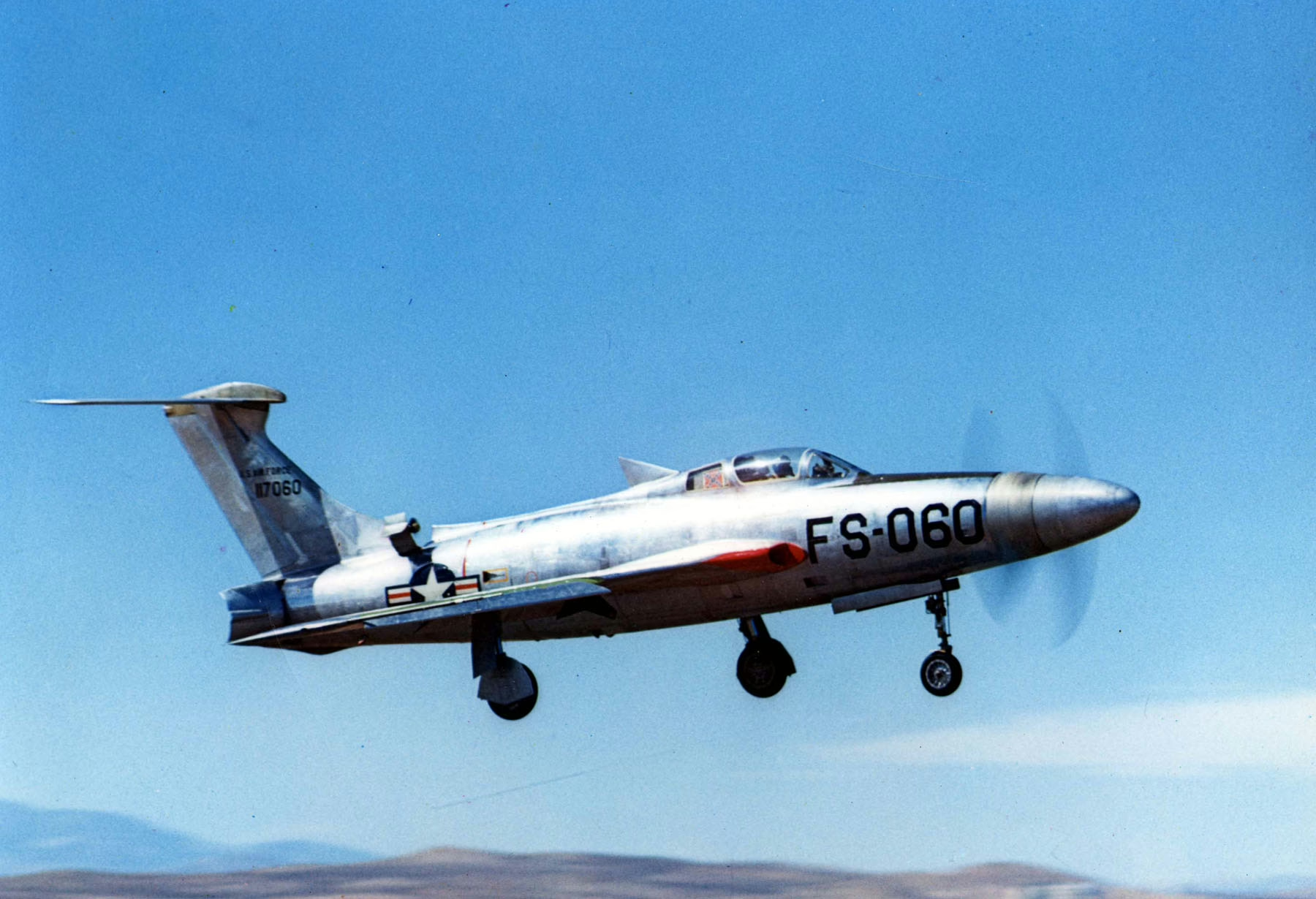
Measuring 51.5 feet long, with a 33.5-foot wingspan and standing 15.4 feet tall, the XF-84H featured several distinctive elements beyond its unique engine configuration. Most obvious was its T-tail with a one-piece stabilizer designed to counterbalance the pronounced forward center of gravity. The stabilizer was positioned to shield the aircraft from propeller vortices, which had proved disastrous on motorized models with the standard RF-84F tail arrangement. The rudder was initially configured to allow 32 degrees of deflection to the right but only eight degrees to the left—this asymmetry being necessary to counteract the tremendous torque generated by the propeller.
An innovative aerodynamic element dubbed the “shark fin” was positioned just behind the canopy. This small triangular auxiliary rudder was designed to improve lateral control during high-speed ground operations during takeoff and landing. It also served as a vortex regulator, diminishing the disruptions caused by the propeller’s wake on the fuselage’s upper section. While the wing retained the general shape of the RF-84F with its 40-degree sweep at quarter-chord, it lacked bulkheads and featured one-piece pivoting slats covering three-quarters of each wing’s leading edge, along with differential flaps designed to enhance roll control, particularly during high-speed ground operations. The air intake, similar to the Thunderflash’s, featured a solid nose cone instead of a plate separated from the fuselage wall.
The air brakes, consisting of two petals, were positioned at the fuselage’s rear section. The landing gear had been modified, especially the nose wheel, which was fitted with an antiquated steering system mounted on a toggle switch instead of foot pedals—and this wasn’t the only surprise awaiting in the cockpit. Pilots had to contend with a throttle that operated over 120 degrees with only a 90-degree arc thanks to a clutch mechanism, and a manually operated dial (!) for progressively monitoring the massive drive shaft’s temperature. Just as the first XF-84H (51-7059) was completed, the program encountered several months of delays when, in February 1954, an Air Research and Development Command commission mandated the installation of an independent backup hydraulic system capable of controlling the aircraft if the primary system failed. Consequently, ground testing could only begin in late summer at Farmingdale and concluded in October 1954. After disassembly, this aircraft was transported by Douglas C-124C to Edwards AFB, arriving in December. It was joined at the Air Force Flight Test Center in February 1955 by the second prototype (51-7060).
~~~ To Be Continued ~~~


